A technical career retrospective part 5
Apple ][+ : July 1981 - 1985
Why this post?
My dive into the world of personal computing ended up changing the direction of my career. The Apple ][+ was the first step along that path. My interests moved away from the mainframes at this point, never to seriously return. Yes, I would continue to learn and work in a mainframe environment, but my personal efforts were dedicated to personal computing from this point in time.
TL;DR
A computer on my desk! Ooh, shiny! (Actually, more of a dull tan color)
The Apple 2 was a wonderful computer, but from a programmer’s perspective, it was full of quirks.
This post is significantly longer than my other posts, simply because I remember so many interesting and unique-to-me features (and limitations) of the Apple.
The world of the Apple 2 was significantly larger than the portion of it I experienced. I’ve avoided mentioning anything that I didn’t personally see or use. Information about those other topics are well-covered elsewhere.
What to buy?
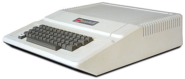
After doing my research, I decided that the Apple 2 would be the best fit. It seemed to be more oriented toward programming, with a wider variety of tools and utilities. I was also attracted to having the slots on the motherboard, where I could add cards for specific purposes.
About the Apple 2
The original Apple 2 could be bought with as little as 4K of memory, but by mid-1981 the expectation was that it would be maxed out with 48K.
The Apple 2, along with the Atarir 400/800 and the Commodore PET, used the 6502 CPU. This was a very inexpensive processor compared to the alternatives at the time. It was also more primitive in many ways - but that helped because systems using the 6502 could be built for less cost than the other processors.
The more sophisticated CPUs used a separate address space for I/O devices, known as I/O Ports. The 6502 instead relied upon “memory-mapped I/O”, which means that your I/O devices were accessed by the CPU at regular memory locations.
As a result of this, while the 6502 could address 64K of memory, it couldn’t actually use 64K. The system needed to reserve memory space for external devices.
Side note
All my comments below are referring to the original Apple ][ and the Apple ][+. There were a number of significant changes made for the Apple //e, Apple //c and Apple //gs that fixed or improved many features.
Documentation
I strongly believe the Apple 2 was the best documented personal computer of that era - and possibly ever. The Apple II Reference Manual provided detailed information about both hardware and software.
The hardware sections included schematics and timing diagrams in sufficient detal to allow people to design add-on devices or new cards to be used in a slot. The software sections provided information on Integer BASIC, System Monitor, Mini Assembler, the 6502 instruction set, “Sweet 16” Emulator, a very detailed memory map, and source code listings for the autostart rom and system monitor; all packed into a very dense 210-page book.
The Apple 2+ also came with a 168-page AppleSoft BASIC manual. This not only provided documentation for the language, but also provided a significant amount of information about the implementation of it.
Memory organization
A CPU with a 16-bit address space has 65536 addresses that it can reference. In hexadecimal, this is $0000 - $ffff. (The typical documentation at the time uses the dollar sign, $, to indicate hexadecimal numbers.)
Each digit represents 4 bits (a “nibble”). Each pair of digits represents 8 bits (1 byte).
The 6502 refers to a memory range of 256 bytes as a page. The page is generally identified by the high-order byte. For example, the addresses $0000 - $00ff is page 0. Page 1 is $0100 - $01ff, and so on.
Special pages in the 6502
A couple of pages are considered special by the 6502 processor. Accessing data on page 0 is generally faster than for any other pages. The 6502 has a special addressing mode for page 0, and instructions using that mode are 1-byte shorter and require 1 less clock cycle execute.
The instructions are 1-byte shorter because the target address is only 8-bits intead of 16-bits. The LDA instruction (load register A) for address $009a would be a5 9a, where the same instruction for address $129a would be ad 9a 12. (Notice that the low order byte is stored first.)
Most instructions using an absolute address require 4 clock cycles, while the page 0 instructions only need 3.
Since these instructions are shorter and faster than non-page 0 accesses, page 0 addresses are at a premium. The Apple 2 tends to use most of page 0, but there are some bytes available and depending upon what you’re doing, you may be able to safely reuse locations generally reserved for the Apple 2 system.
Page 1 is the stack. There are 8 instructions that work directly with the stack. The stack pointer (register S) is an 8-bit register, with as assumed high-order address of $01. Since the stack is only 256 bytes, that puts a hard upper-limit on how much data can be stored there. A subroutine saving all the user-oriented registers when called uses 6 bytes, which limits the system to a call-depth of 42 functions. (In practice, I’ve not written nor seen code use anywhere near that much.)
Special pages in the Apple 2
There are just a couple of memory ranges with special significance in the Apple.
Page 2 ($200 - $2ff) is the keyboard input buffer. Text being entered at the prompt are stored here before being processed. This means that the maximum line length was 256 characters.
Pages 4 - 7 ($400 - $7ff) and pages 8 - 12 ($800 - $cff) are the two text and low-res graphics modes screens. Pages $20 - $3f and $40 - $5f were the high-res graphic modes screens. There are 4 pages in 1K, which means that the text and low-res mode screens were 1K, while the high-res modes used 8K.
Pages $c0 through $cf were reserved for I/O, which included built-in devices like the keyboard and joystick adapter, and including usage by cards in the slots.
Pages $d0 through $ff were used by the ROMs in the system.
Apple 2 flavors
The original Apple 2 came with an “Integer BASIC” built-in. As the name implies, the only numeric type available were 16-bit integers, giving a usable range of -32768 to 32767. It only supported the text and low-res graphics modes. It was fast, but of limited value for anything beyond games.
There was a more complete BASIC available, called AppleSoft BASIC. Along with supporting floating point numbers and a variety of mathematical functions, it also directly supported the hi-res graphics modes and supported a much larger set of commands.
Originally, AppleSoft was distributed on cassette tape or floppy disk, using more than 8K of system memory. This made it unusable at all on the original 4K and 8K Apple 2, and marginally useful on the 12K version.
When the Apple 2+ was release, it had AppleSoft installed in the ROMs.
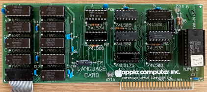
Apple also sold a card into which ROMs could be installed. Inserting an Integer ROM card in slot 0 of an Apple 2+, or an AppleSoft ROM card in an Apple 2, provided the ability to switch between the two versions.
Later, Apple sold a RAM card (The “Apple Language Card”) for slot 0 which allowed either version to be loaded on to it - along with other possible options.
Side note: Neither version of BASIC had a “renumber” command built-in. To renumber your BASIC program it was necessary to run an external utility to do it for you.
Memory-mapped I/O
As an example of exactly what this means, reading address $c000 returns the value of the last key pressed. The high bit is on until address $c010 is read. (The key value remains in $c000 until another key is pressed.)
Reading address $c030 triggers the speaker. Creating a tone required very careful programming to trigger the speaker at a specific frequency. Two side effects of this were that you couldn’t create music in BASIC, you needed an assembler routine for it, and you couldn’t really do anything else while a tone was being generated.
A slot had ranges of addresses assigned to it, based on the slot number. So a card in slot 5 would use different addresses than a card in slot 6. This means that any software on a card had to figure out which slot it was in, and adjust any internal address references.
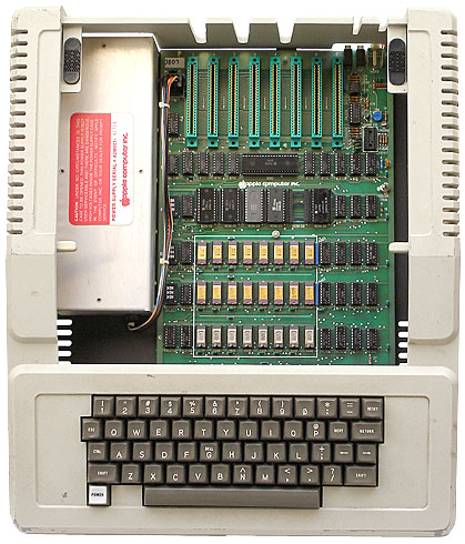
Slot 0 was special, and could only be used by cards designed for it.
Most cards had a conventional slot assigned, but in many cases those conventions were not requirements.
The disk controller went into slot 6.
Printer card in slot 1.
Serial cards were used in slot 2.
It’s not so much that those cards had to be in particular slots as much as most software using them expected to find those cards in those slots.
Slot 7 was also different in that there were some video signals available only to it, but you could still use it for regular cards.
Graphics
The basic screen layout was 24 lines of 40 characters of ASCII text. Switching to low-res graphic changed it to 48 lines of 40 colored blocks. It was the same memory space, but instead of each byte being one character it represented two blocks, top and bottom. Each block was identified by a nibble (4 bits), giving 16 possible colors.
There was also a high-res graphics mode providing a 280 x 192 pixel display.
Additionally, there was the option in the graphics modes of switching the bottom four lines to be of text rather than graphics, allowing a fixed mix of both modes.
The precise memory mapping of “screen coordinate to memory address” is complex. There is no simple formula to transpose any given location on the screen to a memory address without the aid of some type of reference table. I’m not even going to try and describe it here - it’s well-documented in many other places. But as a result, there were a lot of different algorithms and tables created to optimize graphics management.
Display hardware
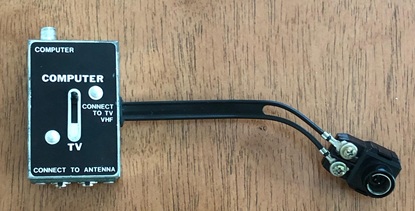
There were two primary options for display terminals, a composite video monitor and televisions. Using monochrome composite video gave the sharpest and most clear text, but monochrome isn’t any fun.
Color composite video monitors were out of my price range at the time, so I went with option two - a color television. Using a color television involved using an RF Modulator to convert the video signal to an NTSC broadcast signal, and then fed into the antenna connector of the television.
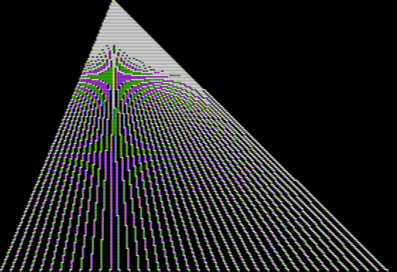
One of the side effects of the hardware used to generate the video signal for the graphics mode was that the display was actually drawing color artifacts.
In text mode, the display circuitry renders text as monochrome.
But in graphics mode, each pixel was of one of 6 colors, depending upon the pixel location. Even numbered pixels were one color, odd numbered pixels another, and two adjacent pixels in most cases showed up as white.
Again, these effects are well documented elsewhere, so I’m not going to describe the specific details here.
Limitations of the 6502
I mentioned above that the 6502 was more primative than the other CPUs of the era. CPUs like the 8080 also had 8-bit registers, but could work with register pairs to work with 16 bit values. The 6502 only had a single 8-bit register for arithmetic operations. This meant that working with anything other than 8 bit values (0 to 255 unsigned, or -128 to 127 signed) required the code be written to do that.
Fortunately, there were plenty of examples available through books, magazines, and newsletters that showed how to effectively work with other numeric types. Enough information eventually became available that a programmer working with a 6502 assembler could even use the floating point routines created for Applesoft within their assembler programs. This information included using the built-in square root, logarithm, trig and other BASIC language functions. With the right macros created, it was like working with a CPU having those instructions built-in.
There were other libraries available for efficiently working with 16 bit integer values. These were particularly valuable when working in the hi-res graphics modes, since the range for the horizontal coordinates for pixels was larger than an 8-bit value. The hi-res screen was 280 pixels wide (indexed as 0 to 279) where an 8 bit index could only go to 255. In order to simplify the programming and improve performance when plotting points, there were some programs that only used the 8 bit indexing for available pixels, leaving the last 14 pixels of each row unused.
Uppercase only
The Apple 2 was an uppercase only system. The keyboard did have a shift key, but it only worked with the numbers and special characters. It didn’t matter whether the shift key was pressed when typing a letter, the exact same key code was sent. The normal character display couldn’t display lowercase letters in text mode, either. However, what the Apple 2 could do was display letters in inverse video.
One technique for the early text editors was to use reverse letters for upper case. Pressing the esc key would shift to upper case mode, causing the text to be displayed as reversed. This worked, but could be very difficult to read.
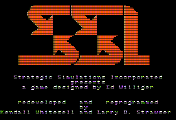
Another available technique was to draw the individual characters as a 7x8 matrix of pixels on the hi-res display. This was slow because eight bytes were needed for each character instead of one.
The characters themselves wouldn’t be all that clear either. With only a 7-pixel width available for a character cell, 6 pixels were usable for characters, making letters like M or W look more like blobs than anything else.
No clock, timer, or any form of programmable interrupt
The base Apple 2 had nothing resembling a clock or timer. Timing loops were written in software and calibrated by calculating the number of clock cycles used by each instruction in the loop. This was critical in some circumstances, less so in others.
Cassette tapes
The cassette tape interface worked by recording a 1 KHz tone for a 1 bit and a 2 KHz tone for a 0 bit. Writing to a tape was done by reading address $c020 at either a 500 microsecond interval to record a 1 bit or a 250 microsecond interval to record a 0 bit. Since the CPU is running at about 1 MHz, 500 microseconds is roughly 500 clock cycles and 250 microseconds is 250 clock cycles.
Reading the tape required reading address $c060 and counting the duration between transitions of bit 7. Since there are speed variances between tape players, the Apple writes a header in front of the data with a known frequence that the software uses to calibrate the read-loop. That calibration is used to determine how many iterations of that loop occur to read a 0 bit. Anything longer than that is read as a 1 bit.
These frequencies average out to about 1500 bits per second of tape, or about 180 bytes per second. A 16K program would take about 2 to 3 minutes to load - assuming it all read correctly.
There were some custom programs available to double or triple the throughput of the cassette interface, but generally required a higher quality tape drive and tape to be truly reliable.
Floppy drives
The lack of a clock or other type of built-in interrupt affected other I/O devices as well.
Reading or writing the floppy drive also used loops for transferring data - but a byte at a time instead of individual bits. The lower level disk code would write a byte to the address for a specific drive, then loop until that byte was “consumed” by the controller, at which time the CPU would write the next byte. Likewise, reading a disk meant reading from an address and looping until the next byte was available.
Actually, the floppy controller was an amazingly flexible design on a number of levels.
Most systems at the time used a 35-track, 10-sector per track encoding on a 5.25” floppy, or about 87K per disk. By using some brilliant encoding, the original Disk II was able to store 13 sectors per track, which was 30% more per disk, or about 113K across the 35 tracks. Later revisions of the controller increased that to 16 sectors per track, or 140K per disk. More sectors per track also meant that fewer head movements were needed to read similar amounts of data, increasing the effective speed of the drive.
The stepper motor for the drive head was also strictly under software control. The typical command to move the head worked in “half steps” - the head needed to be moved twice to change tracks. One of the common copy-protection schemes of the time was to stagger some tracks at three-step intervals to confuse common copy programs. For example, you might write data on track 10, then 11.5, then 13. Trying to read either track 11 or 12 might either fail due to poor signal quality - or possibly work on both, creating duplicate data - but then would fail when trying to read track 11.5 because of the blend of data between tracks 11 and 12. (There was no practical way to physically synchronize the data between two tracks.)
It was also known that many drives could physically work with more than 35 tracks - but it was never guaranteed. For that to work, you needed both drives capable of being moved inward more than 70 half-steps and disks of sufficient quality to reliably store data on those innermost tracks. I seem to remember that virtually all drives could use track 36, but only the later models would go to 40. But since the bits were more crowded along the inner tracks, the diskettes needed to be higher quality as well and were more likely to fail in those locations.
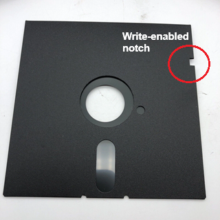
to use the back of the disk
There was no way to interrogate the drive to find the current position of the head. If you kept track of your current location, you could send the right signals to move the head directly to any desired track. But, if for any reason there was a mistake made, your only recorse was to issue the commands to move the head all the way out to track 0 - creating a very distinctive “clacking” sound that every Apple 2 owner was very familiar with. Everytime you booted your Apple, the first thing it did was move the head out 80 half-steps to ensure it was on track 0.
Disk drives and floppy disks were expensive in 1980. The Disk II and controller retailed for about $600, and the 5.25” floppy disks were about $50 for a box of 10(!) For someone earning about $500 / month, you learned every possible trick to get the most out of those disks - including cutting a notch on the other side of the disk, allowing you to flip the disk over and use the back.
DOS
The standard Disk Operating System (DOS) for the Apple 2 was rather primitive - but like the rest of the system, it was extremely well-documented. Buying the controller and drive combo came with a 180-page manual describing everything you needed to know to start working with it.
To minimize the amount of head movement necessary, the disk catalog was placed on track 17 - right in the middle of the disk. Sector 0 contained the bit-map for the disk. If a sector was used, the corresponding bit was set, then cleared when the file was deleted. The rest of that track was used to store the catalog information. There was space for 7 file entries per sector, allowing for 84 files on a 13-sector disk and 105 on a 16-sector disk.
Every file also had a “track/sector list” associated with it, identifying the specific tracks and sectors used by that file, and the order in which they were used. This was external to the catalog entry and could be located just about anywhere on the disk. (Typically, files were allocated a whole track at a time and the track/sector list would be the first sector of that track.)
There were no subdirectories. Everything in the disk was in the main catalog.
File names were “limited” to 30 characters. (A vast improvement over the 8.3 limit common with other systems)
One of the issues with storing all catalog data on that one track is that it tended to wear out that track more quickly than any other track. If you started getting read errors on a disk, that’s where they would show up first. Getting a read error was a sign to copy the disk immediately and to continue working with the new copy.
Apple DOS worked by injecting itself into the command line code. Any line entered starting with a line number was passed directly to AppleSoft. Any other line was inspected first by DOS to see if it was a valid command, and processed if found. Everything else was passed through to AppleSoft.
When trying to use the disk in a program, such as to read a file containing data, DOS was called by using the PRINT statement with ctrl-D as the first character of the string. DOS intercepted the “character out” routine. If the first character was ctrl-D, then DOS would process that string as a command.
Program listings wouldn’t show a literal ctrl-D, so it was common to assign that character to a variable or to use the CHR$(4) function call within your code to show that it was a DOS command being issued.
There were utilities available allowing commands to be renamed (e.g. CAT, DIR, or LS instead of CATALOG for getting a listing of files on the disk), which worked, provided you didn’t override an existing command.
One of the known issues with DOS was that it buffered sector reads. DOS would read a sector into its buffer, then copy that data to its destination. This would slow the read process long enough to prevent the CPU from being ready to read the next sector as the disk spun under the head. As a result of this, sectors were usually interleved on the disk. The second sector of a file might be anywhere from 4 to 7 sectors after the first. Reading a full track of data required the disk rotate 3 - 7 times before the data could be completely read.
Each track held 3,328 bytes of data, so a 16K program needed 5 tracks. This added 5 track transitions as part of the loading process. All this movement and intermediate processing made loading programs or reading data files take significantly longer than what the hardware was capable of doing.
RDOS
There were multiple alternatives to Apple 2 DOS that were intended to improve performance.
I used one called RDOS, that optimized the read/write process at the expense of some of the flexibility of DOS. I worked with it for a while, and it was amazing speed-wise for loading and running programs. Files were allocated strictly in order. Instead of files having a track/sector list, file space was identified by a starting track/sector location and length.
Loading programs and data wasn’t buffered. When reading data (or loading programs) the data was written directly to the destination address. This allowed an entire track to be read in one rotation of the drive.
Also, when moving the head between tracks, sector 0 of the next track was created at the location in front of where the head was going to be when the move from the previous track finished. Instead of waiting an average of a half-rotation to get to sector 0, the drive could start reading almost immediately.
What was given up by doing this is the flexibility of a more general purpose file system. When a file was first created, it created a “slot” for that file. Files were not allowed to grow beyond that size without it being moved to a new slot. However, you could specify a size when initially creating a file to pre-allocate space, giving room for growth. This made these disks poorly suited for development, but impressive for distributing software.
Hard drives
There was a 5 MB hard drive available in 1981 for $5000. Since Apple 2 DOS was designed around disks having either 113 KB or 140 KB of space, the hard drive was divided into 35 logical drives. I saw one once, was extremely impressed with the speed, but could never come anywhere close to even thinking about buying one.
Apple 2 keyboard
The physical keyboard on the original Apple 2 had one massive usability problem.
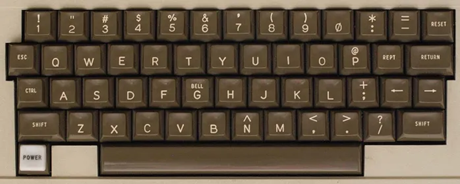
The RESET key was on the top right of the keyboard, next to the = and directly above RETURN. It was a common mistake to hit it accidentally.
On the Apple 2+, the spring on that key was noticably stiffer than the other keys, but I’ve always been heavy on the keyboard so that never really protected me.
During normal operations working in BASIC, it wasn’t too horrible to hit it by mistake. It typically did a “warm reset”, which stopped a running program, but didn’t fully reset / reboot it. Usually the worst that would happen would be that you would lose the line of code or command being entered.
However, it was much worse when working in one of the assembler editors. In most cases, it would exit the editor and return to the command prompt, potentially losing what was being edited.
There were a couple different solutions available. I bought a special adapter that was inserted between the keyboard cable and the motherboard. It had a push-button switch that you would run out the back, and that would become the reset button.
Heat issues
An Apple 2 case with three or four cards inserted was very crowded. Over time, ambient airflow was insufficient to keep the system cool enough to prevent problems.
One of the most common problems was that the memory chips would heat up and expand, forcing themselves out of their sockets.
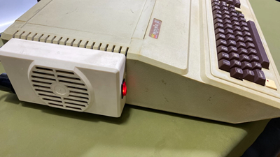
When the system failed, the first diagnostic step was to remove the top and press the RAM and ROM chips down to ensure they were seated properly.
There were third-party fans that could be attached to the outside of the case to improve airflow. Mounting one or two on the sides of the case generally avoided any future problems.
Why was all this important?
Why did I need to learn all this? Because it was required knowledge when programming the Apple 2 if you wanted software that performed well. Anytime you’re programming in assembler, you absolutely need to understand the CPU, the instruction set, and how you use it to create higher-level units of code.
In the era before protected mode operating systems, you were also responsible for your own memory management. There were usable areas of memory, and memory to be avoided, and memory that was usable if you knew exactly what you were doing.
Performance was always a constraint. The 6502 was clocked at (roughly) 1 MHz. (Actually, 1.023 MHz) With a typical instruction taking an average of 3 clock cycles, you can execute about 300,000 instructions per second. A simple 8 bit addition of two separate bytes of memory requires 11 clock cycles means that you can only perform about 90,000 additions per second. Performing multibyte operations such as 16-bit or floating point values brings this rate way down, to about 100 floating point multiplications per second, or 10 trig functions (e.g. sine, cosine or tangent) per second.
The more you learned about the hardware, the better your software was going to be - and if you had any intent of producing a commercial product, these were exactly the types of things you needed to learn.